Lab 4: Motors and Open Loop Control
Prelab
Wiring Discussion
This lab focuses on integrating two DRV8833 dual motor drivers into our system so that we have greater control over how we drive the car as opposed to using the car’s original control PCB. Each of these motor drivers has the potential to drive two motors, but in order to increase the current supply to either motor, both channels on a singular motor driver were combined. This allowed for the motors to produce a larger torque. A diagram of this circuit is shown below.
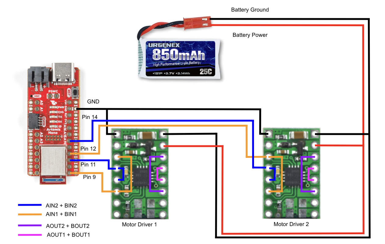
As can be seen in the diagram above, four pins are required to control these two motor drivers. This is because each of the combined channels, AIN1 + BIN1 and AIN2 + BIN2 on both motor drivers, requires an independent Pulse Width Modulation (PWM) signal, which in turn drives the motors of the car. For the first motor driver, I use Pin 9 for the IN1 channel and Pin 11 for the IN2 channel. For the second motor driver, I use Pin 12 for the IN1 channel and Pin 14 for the IN2 channel. The outputs of both motor drivers, AOUT1 + BOUT1 and AOUT2 + BOUT2, got to their corresponding motor’s power and ground, allowing the Artemis to control the motors through the dual motor drivers.
I chose to use these pins as they are on the same side of the Artemis board and more towards the lower half of the board. This allowed me to maneuver the board more freely because all the motor driver connections were centered around one corner.
Importantly, the diagram above illustrates that a Li-Ion 3.7V 850mAh battery is used to power the motors, which has slightly more capacity than the Li-Ion 3.7V 750mAh battery used to power the Artemis. It is vital to separate these two sources of power because the motors can draw a large amount of current, and this current could potentially cause a lot of EMI for the microcontroller if they were looped together into the same power circuit. By separating these components, we are attempting to reduce the EMI exposure of the microcontroller.
Lab Work
Testing Setup
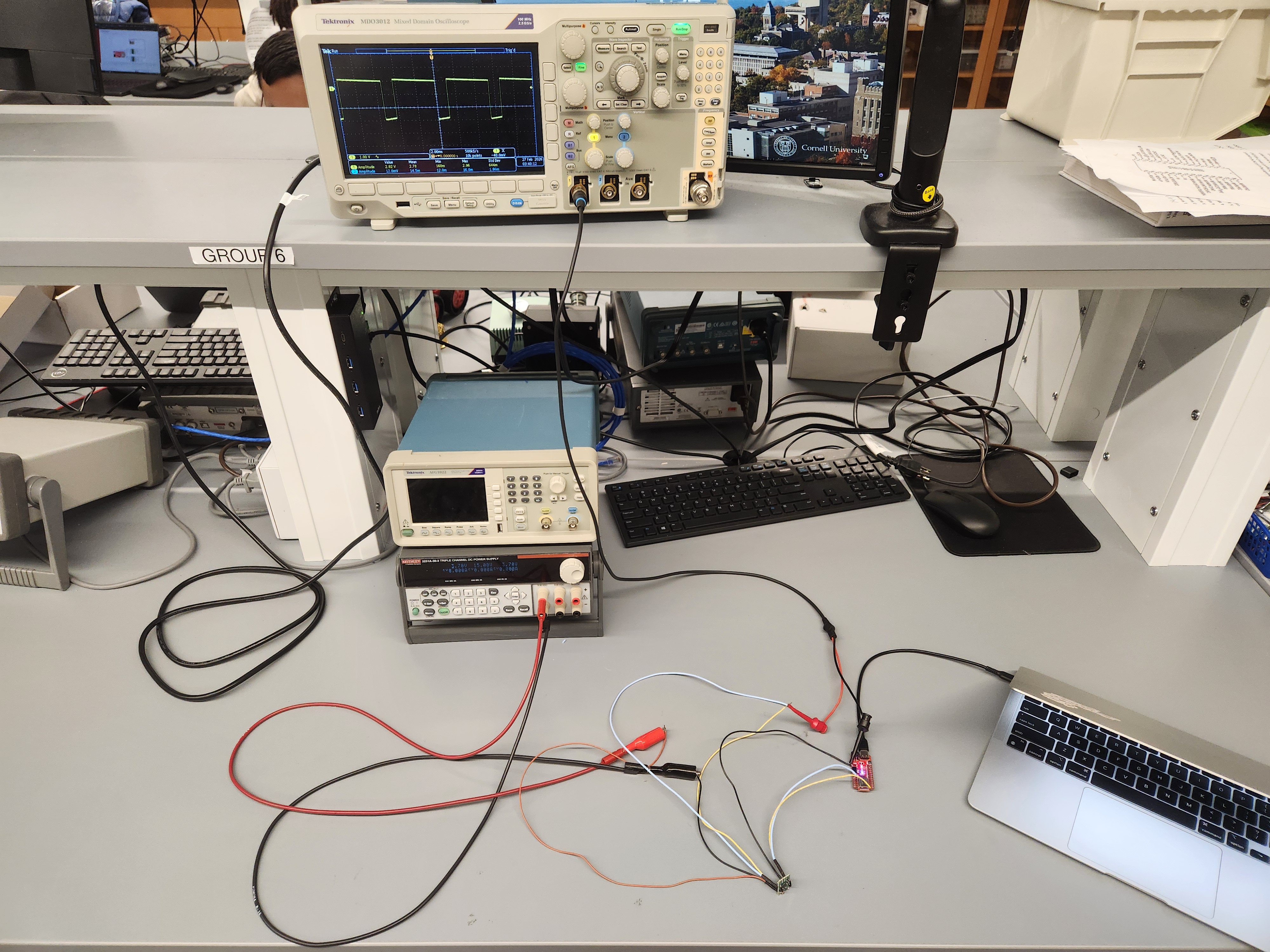
Before soldering the battery to the motor drivers, I needed to ensure that they were outputting the expected signal when given a certain input from the Artemis board. In order to do this, I tested each of the motor drivers by connecting them to a DC power supply and monitoring their output with an oscilloscope. I set the power supply 3.7V to simulate the voltage of the Li-Ion battery that will power the motors in the final configuration. This lab setup is pictured below.
You may notice that one of my input pins to the motor controller shown is not one of the pins that I described in the previous section. This is simply because I wanted to test different pin connections, as I found that some of the pins automatically go high when the Artemis board boots up. Pin 9 is one of these pins, and through this experimentation I found out that I have to set it low before in the setup() portion of my code in order to change the PWM signal it outputs later.
Testing PWM Output (Include the code snippet for your analogWrite code that tests the motor drivers)
When testing to see if the motor drivers produce the correct output, I used the analogWrite() function in Arduino to control the PWM output of Pins 9, 11, 12, and 14. For example, with the code shown below, I tested if the motor controllers were able to output the correct duty cycles of about 79% (200 out of the 255 maximum) and 40% (100 out of the 255 maximum).
 analogWriteResolution(8);

 analogWrite(9, 0);
 analogWrite(11, 100);
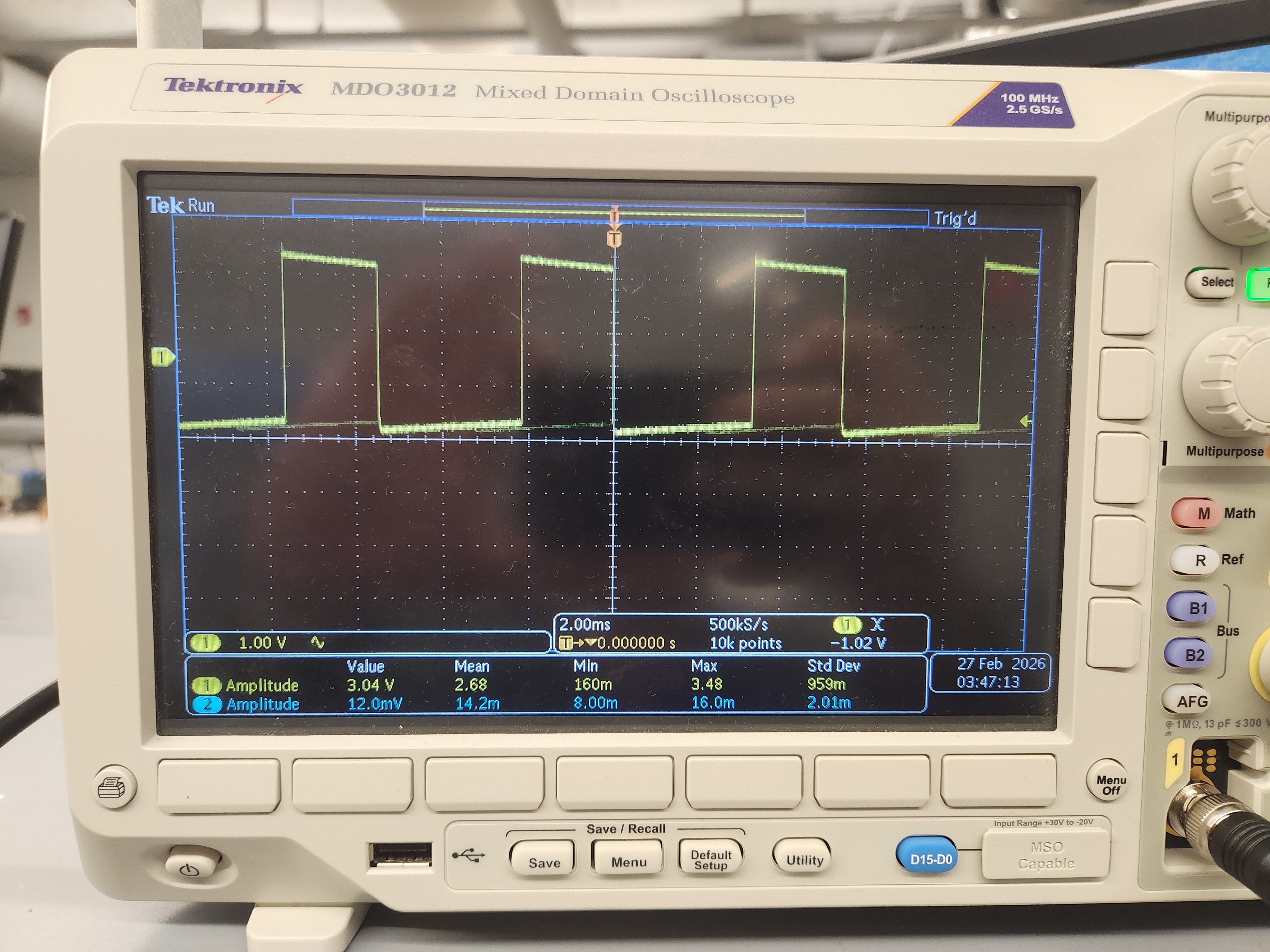
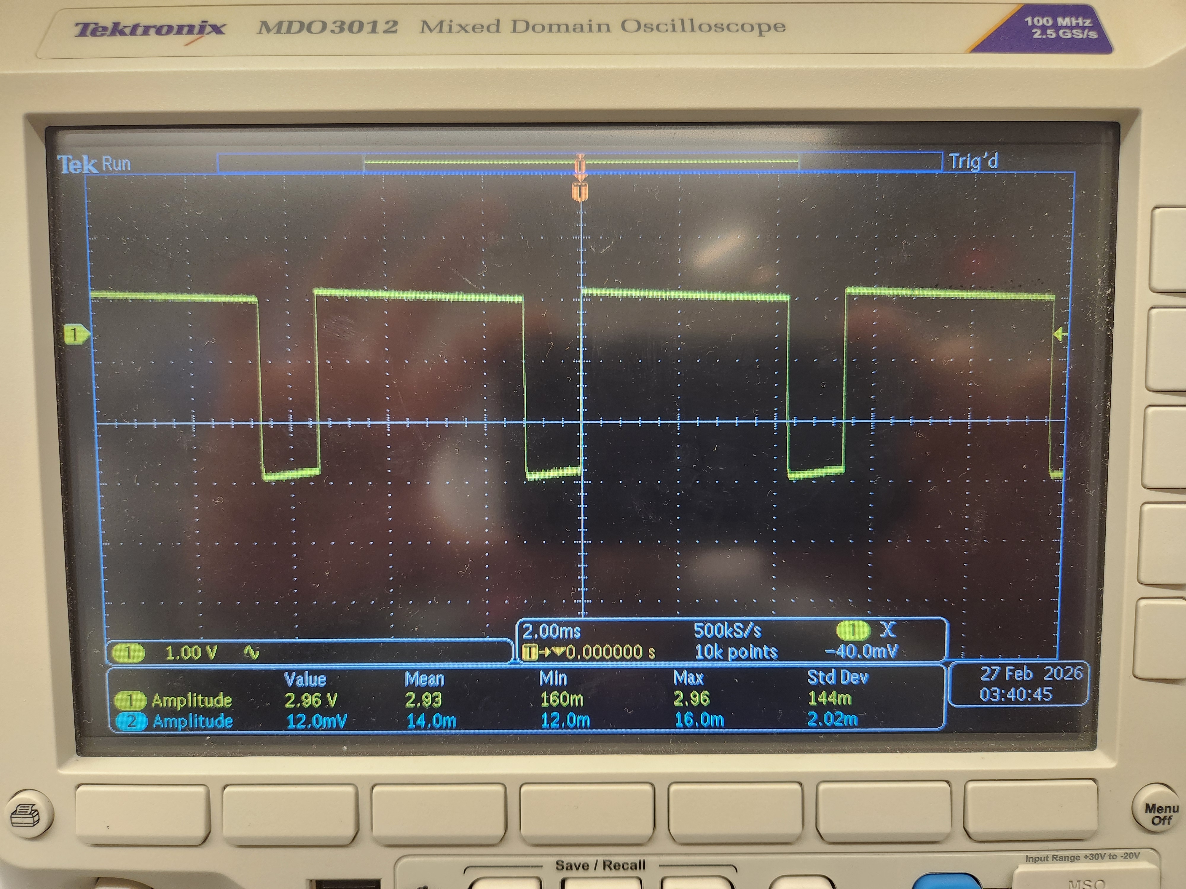
For each motor driver, I commanded one of the pins associated with it to output either 100 or 200 as the PWM signal and set the other pin as 0, and then tested the opposite as well. This was done with very similar code to that shown above, just requiring me to change the pin numbers and PWM value in the function call.
The output of these tests can be seen below. The first image shows the motor driver output when given an input of 100 out of 255, and the second image shows the output from a 200 out of 255 input.
It is interesting to note that the Artemis has different PWM resolutions. When the PWM resolution is set to 8, as I did here, PWM signals can be between 0 and 255. When it is set to 16, however, PWM signals can be set anywhere between 0 and 65535. Resolution this high doesn’t seem necessary for the robot in this lab, but it’s good to know that the option is there if I want to develop very fine tuned inputs into the system later on.
Testing Functionality
After ensuring that the motor drivers were outputting the expected values, I each of them to one of the car’s motors one at a time. The motor drivers, and the motors as well, were still powered by the power supply at this point. I tested the behavior of the motors when given the following command continuously:
 analogWrite(9, 100);
 analogWrite(11, 0);

 delay(2000);

 analogWrite(9, 0);
 analogWrite(11, 0);

 delay(2000);

 analogWrite(9, 0);
 analogWrite(11, 200);

 delay(2000);

 analogWrite(9, 0);
 analogWrite(11, 100);

 delay(2000);
The result of this test can be seen in the video below.
While it may be hard to see in the video, the difference in speeds can be heard by the change in volume of the motor.
Fully Integrated System
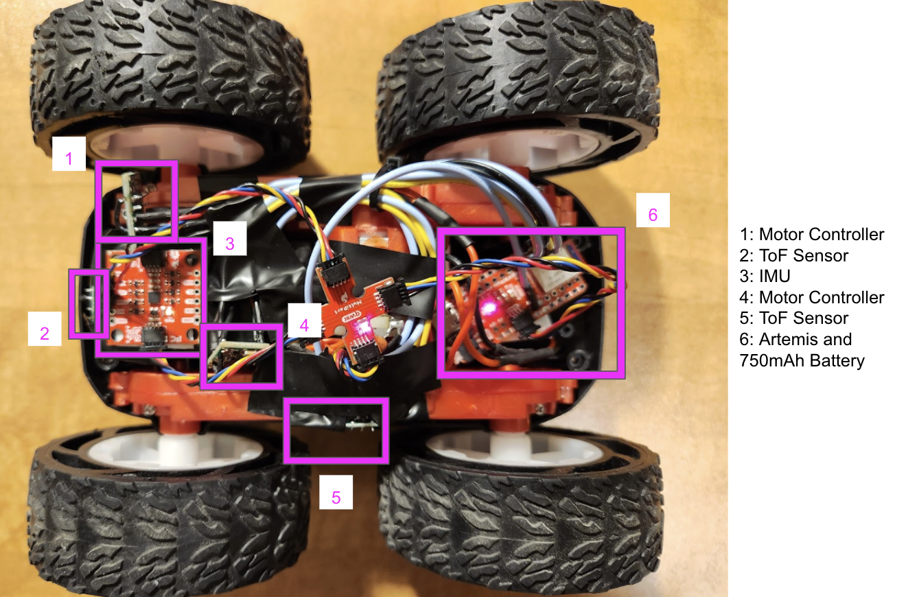
The natural next step was to use the Li-Ion battery to power the motors instead of the DC power supply. How I decided to place all devices on the car is shown in the image below.
The result of this setup can be seen in the video below, depicting my car running independently from the given controller, the DC power supply, or a direct connection to my computer.
PWM Input Limitations
Through experimentation, I found that for any PWM input lower than 30 out of 255 will cause the car to stall when attempting to move forward from a stopped position. This value is a very low boundary for the minimum necessary PWM input to move from a standstill because after it initially causes the car to move, it stalls again. This behavior can be seen in the first video below. The second video illustrates how, with a PWM signal of just 25, the car no longer moves.
In order to have the car rotate consistently, the Artemis needs to command a PWM signal that is no lower than 180 out of 255. This value produced a slight rotational movement, but it also caused the car to move forward. It is possible that this has to do with the calibration of the motors, which I will discuss in the following section. Ideally, when attempting to rotate on-axis from a standstill, the PWM signal is greater than at least 200 to get really good rotation. The video below shows the slight rotational movement when the car is given a PWM signal of 180.
Calibration Discussion
As mentioned above, one motor seems to be more impacted by a PWM input than the other. This could be an issue because when given the same input, the motors should allow for the car to drive in a straight line, which was not the case. In order to overcome this issue, I decided to multiply the PWM input of the motor that seemed to lag behind by a value greater than 1. This caused its PWM input to be slightly larger than its counterpart’s, which resulted in more ideal behavior.
After some experimentation, I found that 1.15 was a good scaling factor for my car. The video below shows the robot moving in a relatively straight line for 6 feet with this scaling factor.
Open Loop Control
While moving in a straight line is important, it isn’t very fun. Instead, I made my robot car move in a slithering pattern like a snake by predetermining the PWM inputs and the timing for each of the inputs. It even drifts a little bit!
The code I ran in order to do this flows from one set of PWM inputs to another after a certain amount of time has passed. Below is some pseudo code of my open loop control.
if (time passed <= 600 us) { // the first turn
    analogWrite(9, 75*1.15); // very low duty cycle
    analogWrite(11, 0);
    analogWrite(12, 220); // almost full duty cycle
    analogWrite(14, 0);
} else if (time passed <= 1200 us){ // the second turn is the reverse of the first
    analogWrite(9, 220*1.15);
    analogWrite(11, 0);
    analogWrite(12, 75);
    analogWrite(14, 0);
} else { // back to the first turn
    analogWrite(9, 75*1.15);
    analogWrite(11, 0);
    analogWrite(12, 220);
    analogWrite(14, 0);
}
This code resulted in the behavior shown in the video below.